power flame burner wiring diagram
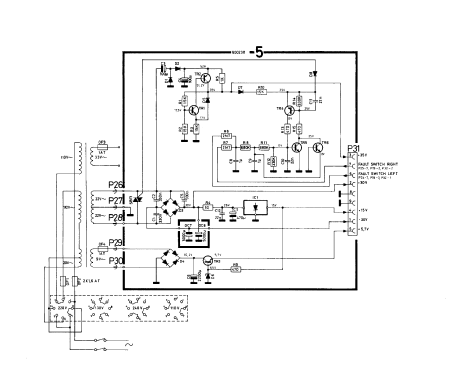
The Power Flame Model CGO dual fuel burner presents an optimum state-of-the-art design for maximum combustion efficiency and operating dependability These packaged combustion. 61 Refer to wiring diagram shipped with burner and typical wiring diagrams Figures 5 and 5A.

Power Flame
The fuel oil pump is remote on all.

. If supplied 62 Electrical installation must be made in accordance with National Electrical Code and applicable local codes. General 211 Before beginning installation carefully study these. 62Electrical installation must be made in accordance with the NEC NFPA 70 or Canadian Electrical Code Part 1 and applicable.
14 Pics about Diagram together with GM HEI Ignition Module Wiring Diagram. Comprehensive wiring diagrams are furnished with each burner. Because each field application is unique the final burner set-up.
Loose connections or faulty wiring. Tighten all terminal screws and consult. The two power leads black and white are located inside the burner panel.
Reset and determine cause for apparent flame failure. We manufacture a wide range of commercial burners industrial burners boiler burners. Each Power Flame VECTOR burner is factory test fired to ensure that components and systems.
Special panels for wall mounting or free standing applications are available at extra cost. Diagram together with GM HEI Ignition Module Wiring Diagram. FD FDM Installation Operation Manual - POWER FLAME INCORPORATED 6 2.
WIRING 61 Refer to wiring diagram shipped with burner. 61 Refer to wiring diagram shipped with burner and typical wiring diagrams Figures 5 and 5A. The two power leads black and white are located inside the burner panel.
OR_6319 Power Flame Burner. Flame safeguard control safety switch tripped out. Each Power Flame VECTOR burner is factory test fired to ensure that components and systems are functional.
INSTALLATION 21 Burner Mounting. 61 Refer to wiring diagram shipped with burner and typical wiring diagrams Figures 5 and 5A. Click here for the Power Flame library.
Atwood Furnace Wiring Diagram. 6 WIRING 61 Refer to wiring diagram shipped with burner. Panels and burners are fire tested before shipment.
The Power Flame burner is a model WJR50A-15C which has controls for modulation. On gm hei.
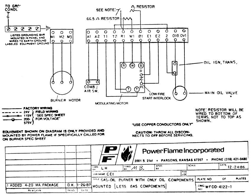
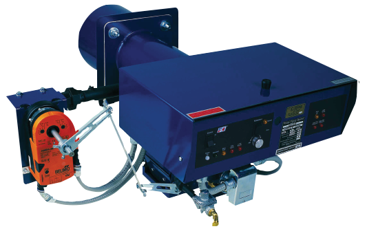
Gas Oil Burner With Only Oil Components Mounted Less Gas Components

The Effect Of Swirl Burner Design Configuration On Combustion And Emission Characteristics Of Lean Pre Vaporized Premixed Flames Sciencedirect

Schematic Diagram Of Tlc Fid Iatroscan Equipped With Fid And A Fpd Download Scientific Diagram
15 Watt Sender Empfanger 15 24b 124 Mil Trx Militar Verschiedene

Honeywell Ra116a Protectorelay Oil Burner Controls Installation Guide Manuals

Furnace Power Flame Incorporated Oil Burner Gas Burner Circuit Board Graphics Schematic Combustion Png Pngegg

Articles

Burner Sets Procesni Com

Power Flame Cici Boiler Rooms
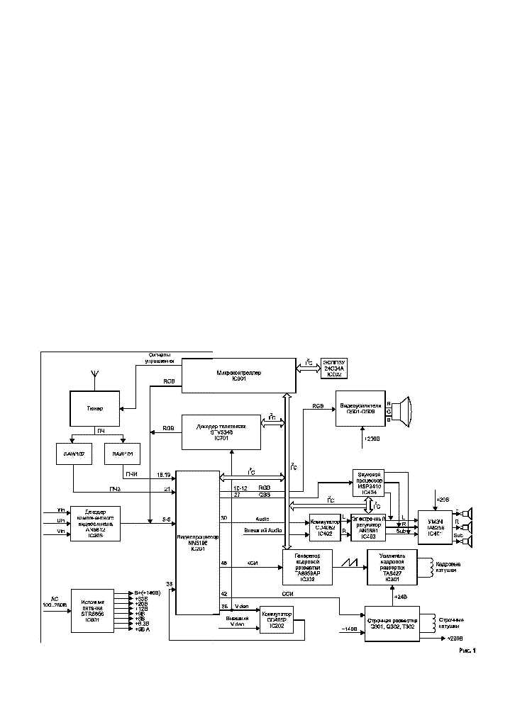
Akira Chassis 5n11 Sch Service Manual Download Schematics Eeprom Repair Info For Electronics Experts

Power Flame

Combustion And Flame Front Morphology Characterization Of H2 Co Syngas Blends In Constant Volume Combustion Bombs Energy Fuels
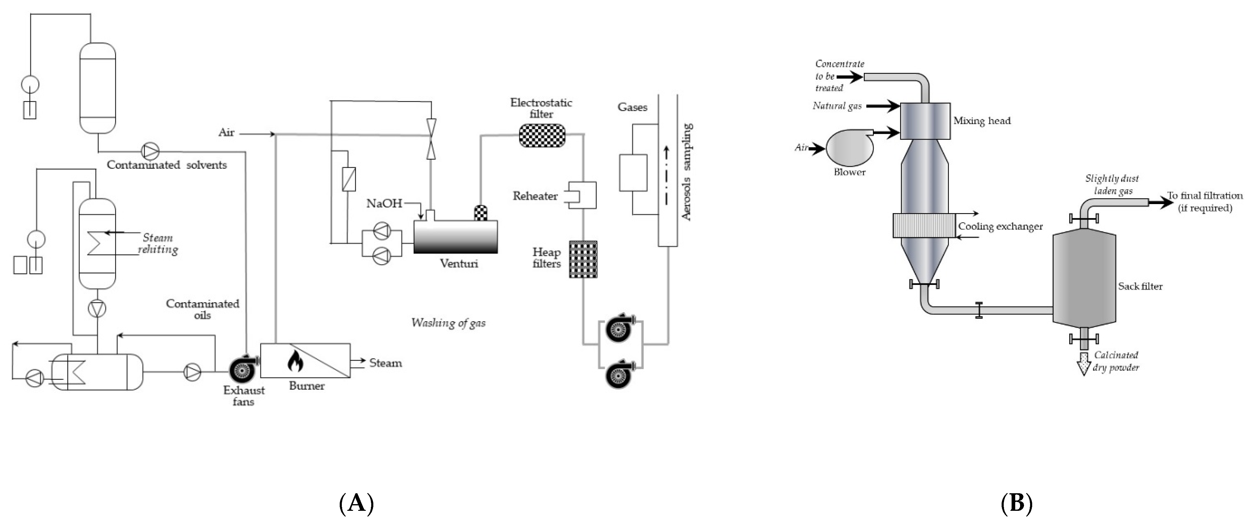
Energies Free Full Text Methods Of Thermal Treatment Of Radioactive Waste Html
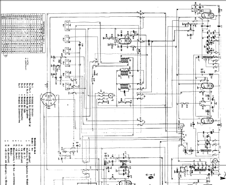
Beomaster 2200 1601 Radio Bang Olufsen B O Struer Build
Powerflame Boilerdata Com

I Have A Burnham Boiler With A Power Flame C2 G Burner And It Will Not Start The Burner Until The Fluid Temperature

Flame Failures And Recovery In Industrial Furnaces A Neural Network Steady State Model For The Firing Rate Setpoint Rearrangement